I’ve been plugging away at my laptop for 8 years and its finally decided that its had enough of me. Wasn’t 100% dead, but was quickly trying to give up. Snooping around the shops for a replacement I came across the concept of SFFPC aka Small Form Factor PC.
The overarching principal of SFFPC was performance density and I thought this would be a great adventure to undertake. But I didn’t want to just make any old SFFPC, I wanted to make the smallest! So here I present to you a fully capable PC toping out at 2.97L!
Design
Listed below is table of the parts the were stuffed into Mochi. There were 2 things that drove my selection process: 1. Component form factor and 2. Thermal efficiency.
Packing high performance components into a tight form factor is a recipe for thermal throttling, so I wanted to select components that were efficient not only in volume, but also in performance per TDP (thermal dissipation power). The AMD Ryzen 5 7600 has a TDP of 65W and the RTX4060 has a TDP of 115W. Which honestly is an amazing thermal performance value. I also plan to slight undervolt both to help reduce the thermal load.
Compared with my current laptop the result is an 8x improvement, bringing me back to what Moore’s law promised.
| Item | Part | Notes | Link |
| Motherboard | Gigabyte A6201 AX AMT MITX | The central core of the PC is the motherboard. The smallest form factor available is ITX. | https://www.gigabyte.com/Motherboard/A620I-AX-rev-10#kf |
| CPU | AMD Ryzen 5 7600 | AMD came out with the AM5 in Fall 2022. I knew that for future upgradeability I wanted the latest chipset. | https://www.amd.com/en/products/processors/desktops/ryzen/7000-series/amd-ryzen-5-7600.html |
| GPU | Zotac Nvidia RTX4060 8GB Solo | One of the smallest latest generation GPUs available. | https://www.zotac.com/us/product/graphics_card/zotac-gaming-geforce-rtx-4060-8gb-solo |
| DDR | Silicon Power DDR5 2x16GB 5600MHz | https://www.silicon-power.com/web/us/product-Zenith_DDR5_Gaming_UDIMM | |
| PSU | HDPLEX 250W GaN | Got to love gallium nitride. I’m sure its an assembly/reliability nightmare, but you pay a premium for tiny high power density. This little PSU is fantastic! | https://hdplex.com/hdplex-fanless-250w-gan-aio-atx-psu.html |
| CPU Fan | Noctua AM5 low profile | The shortest cpu cooler that I could find with actual specs. Technically the ITX profile could hold a 120mm fan, but I couldn’t find a heatsink design that didn’t raise its height above the DDR sticks. | https://noctua.at/en/nh-l9a-am5 |
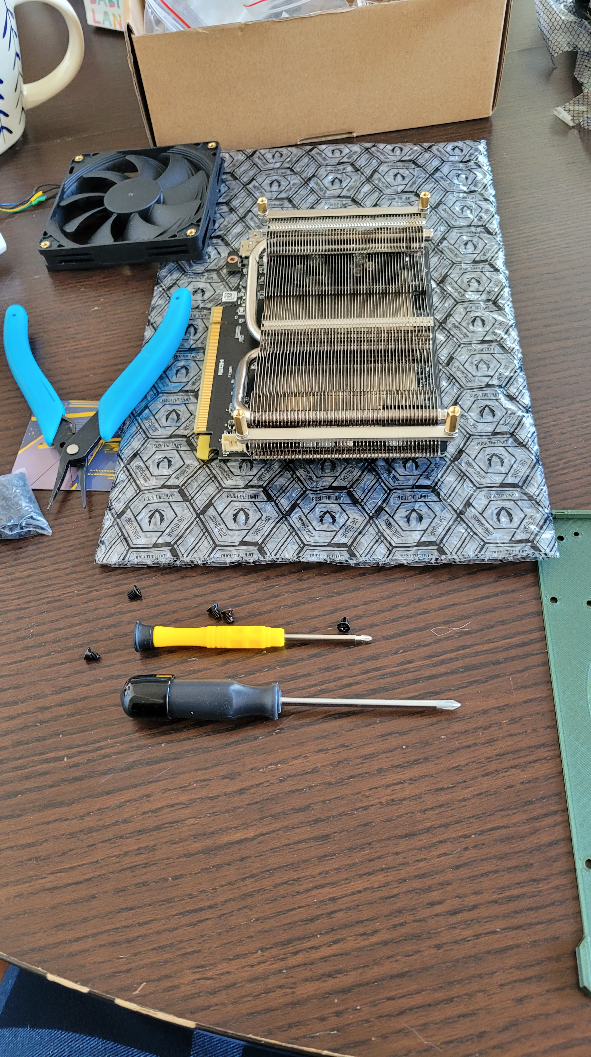
| GPU Fan | Noctua 90mm fan | Every mm counts. The GPU shroud takes way to much space so I replaced the fan with a lower profile one. | https://noctua.at/en/nf-a9x14-pwm-chromax-black-swap |
CPU selection
Figured I’d spend a little more time on the CPU selection process. As mentioned previously TDP is important in SFFPC builds. The other consideration is not breaking the bank.
Looking at the current benchmark of my laptop I knew that I wanted to have at least a 7x improvement to get back to the present. That meant a performance of ~22000 (what are the units?!?). Looking at cpu benchmark I carefully scrutinized the value scatter plot to find what I needed.

Configuration
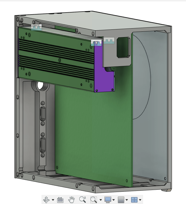
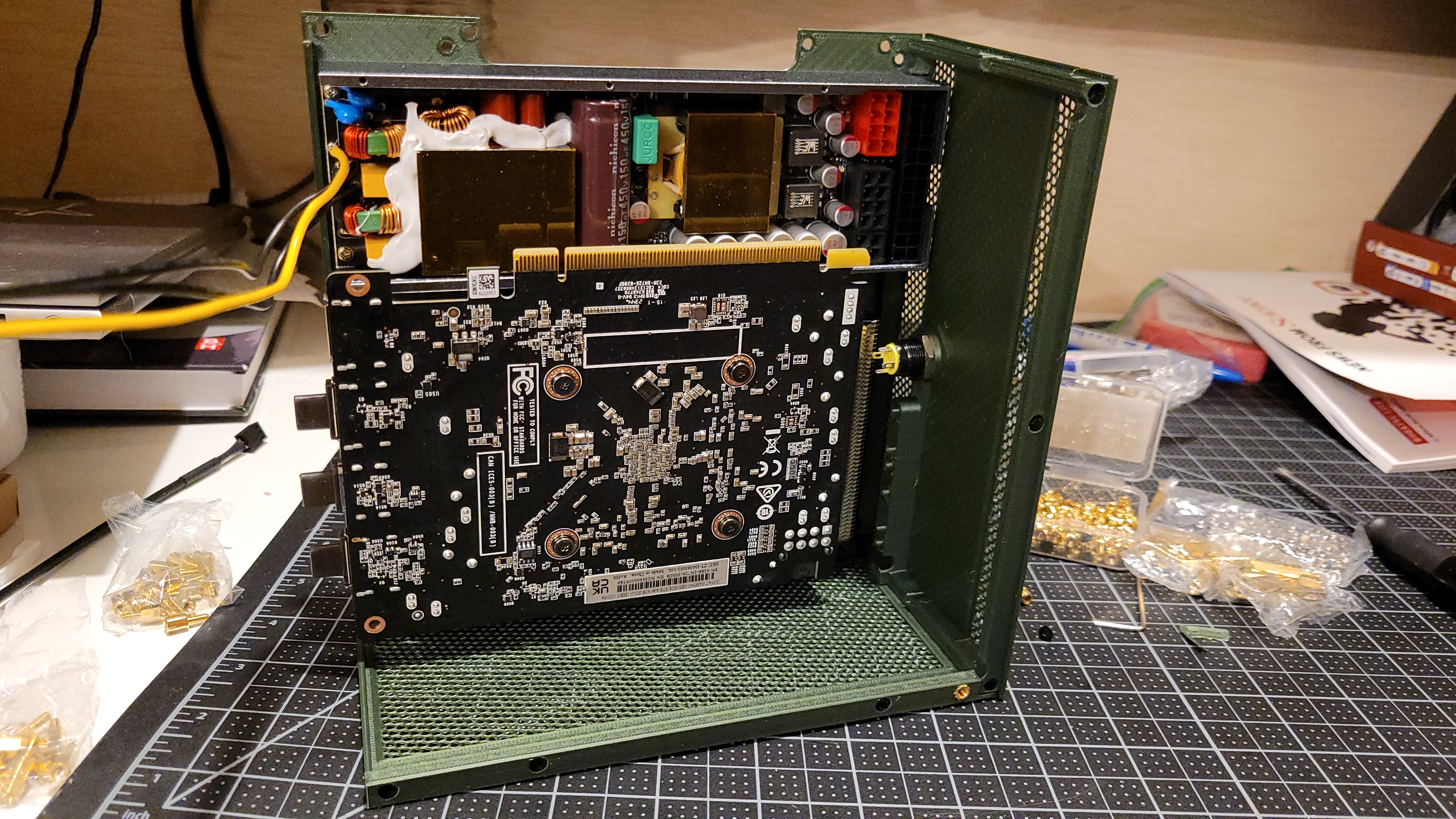
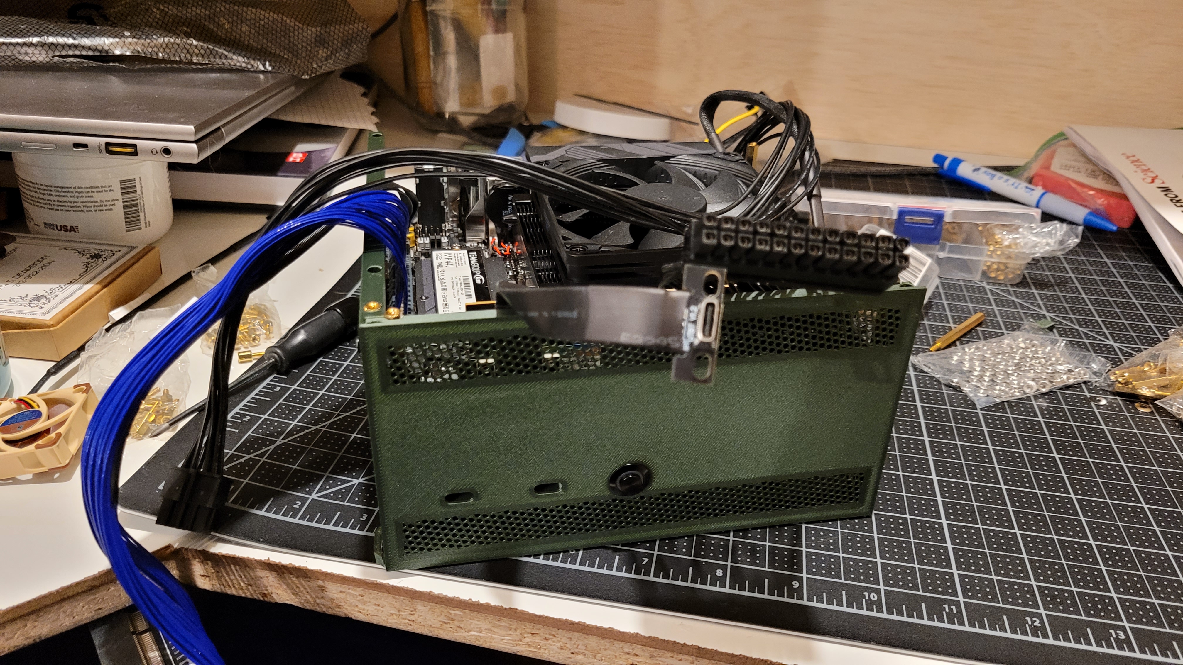
When I started the modeling of my case I began by playing around with a bunch of component configurations. The motherboard, GPU, and PSU are the 3 main components that define the total case volume and thus finding a configuration that minimized overall volume was somewhat difficult. I eventually settled on what is considered a ‘sandwich’ case. The CPU cooler sits on one side and the GPU sits on the other with a PCIE riser cable interconnecting the two.
Unlike sandwich cases you can buy I purposefully didn’t design mine with a spine. For cases that included a spine the idea was that you would mount your motherboard to this metal framework and it would be the primary load carrying path. However adding a spine and its associated mounting features eats into precious cubic mm’s so I reasoned I could do without it if I made my primary load bath the motherboard itself. Compared to the stamped sheet metal spine, the fiberglass PCB, CPU/VRAM backing plate is just as stiff, if not stiffer given its thickness and framework.
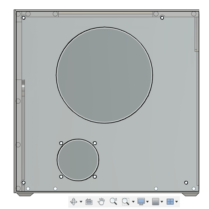
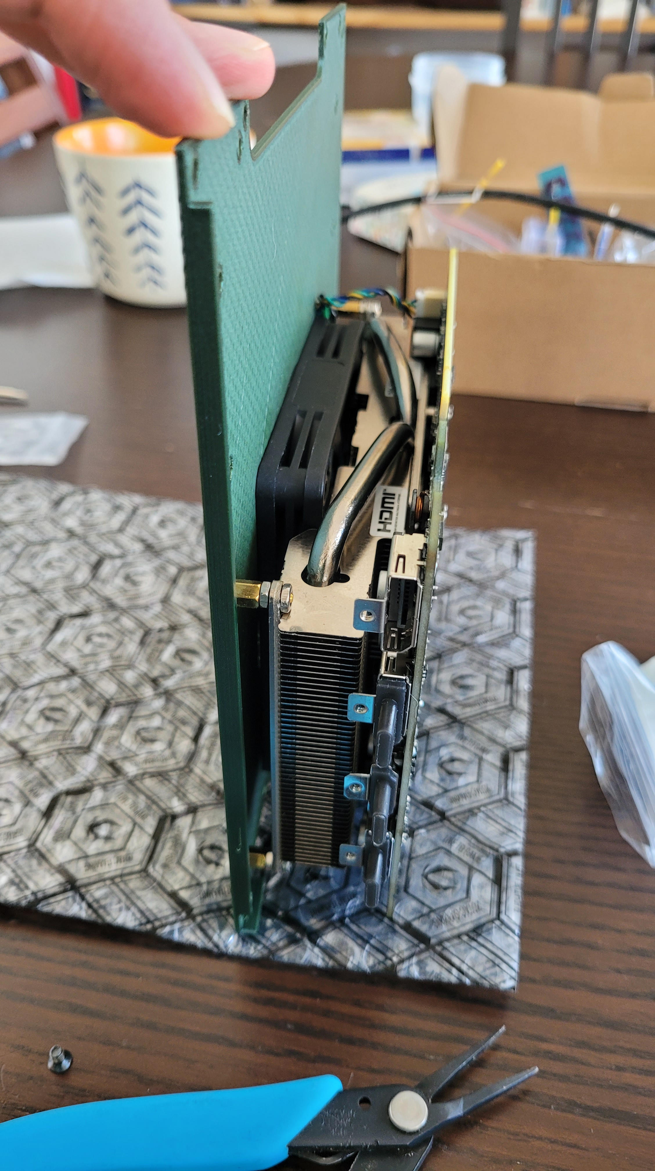
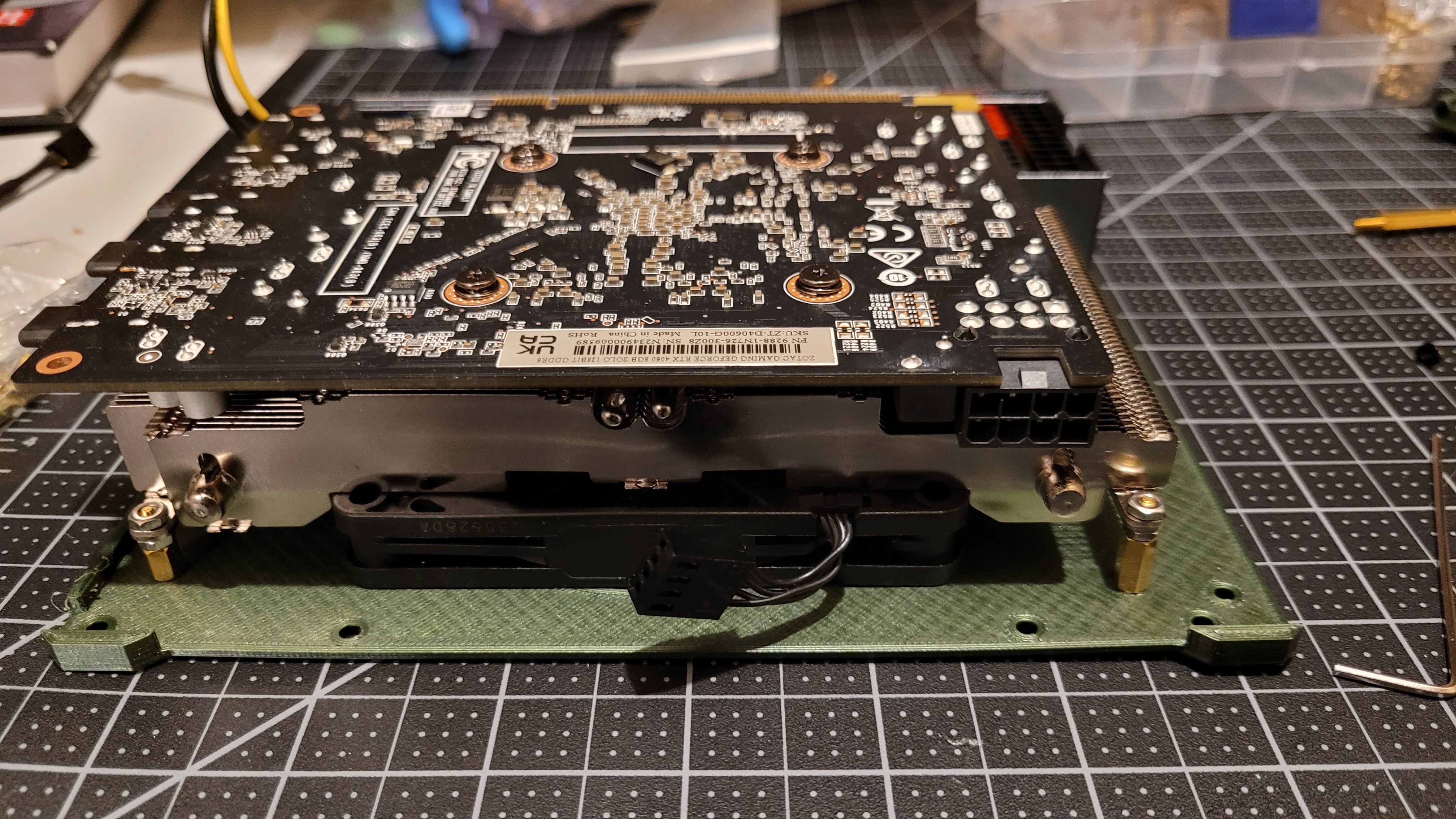
Mounting the GPU was tricky as well. Traditionally these devices are mounted to PC cases utilizing a metal bracket along the IO ports that slots and screws into the back of the case. Although this metal bracket is small, it adds a lot of height to the overall sub-assembly. Instead what I did was I de-shrouded the GPU and re-used the heatsinks 4 mounting screws to attach it to a side panel of my case. The heatsink itself is bolted to the GPU’s own backing plate providing a very rigid way to integrate the assembly to the case.
I selected mounting the GPU’s heatsink to the side panel over utilizing the GPU’s PCB mounting holes because >90% of the mass of the GPU is situated within the heatsink. By anchoring the heatsink I didn’t have to worry about the GPU’s pcb flexing and causing clearance issues.
CAD Model
As per usual I leveraged Fusion360 for my cad design. Went through a bunch of iterations until I got a working model I was happy with. Some screenshots below.
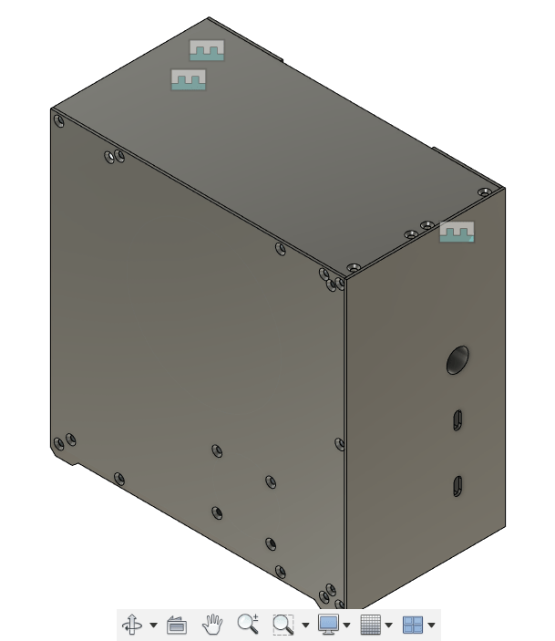
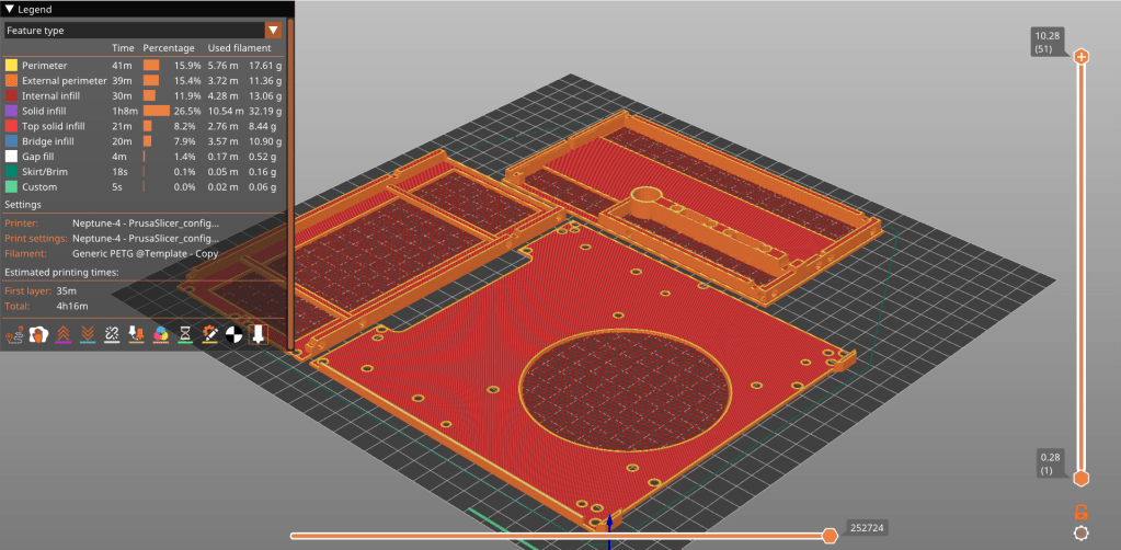
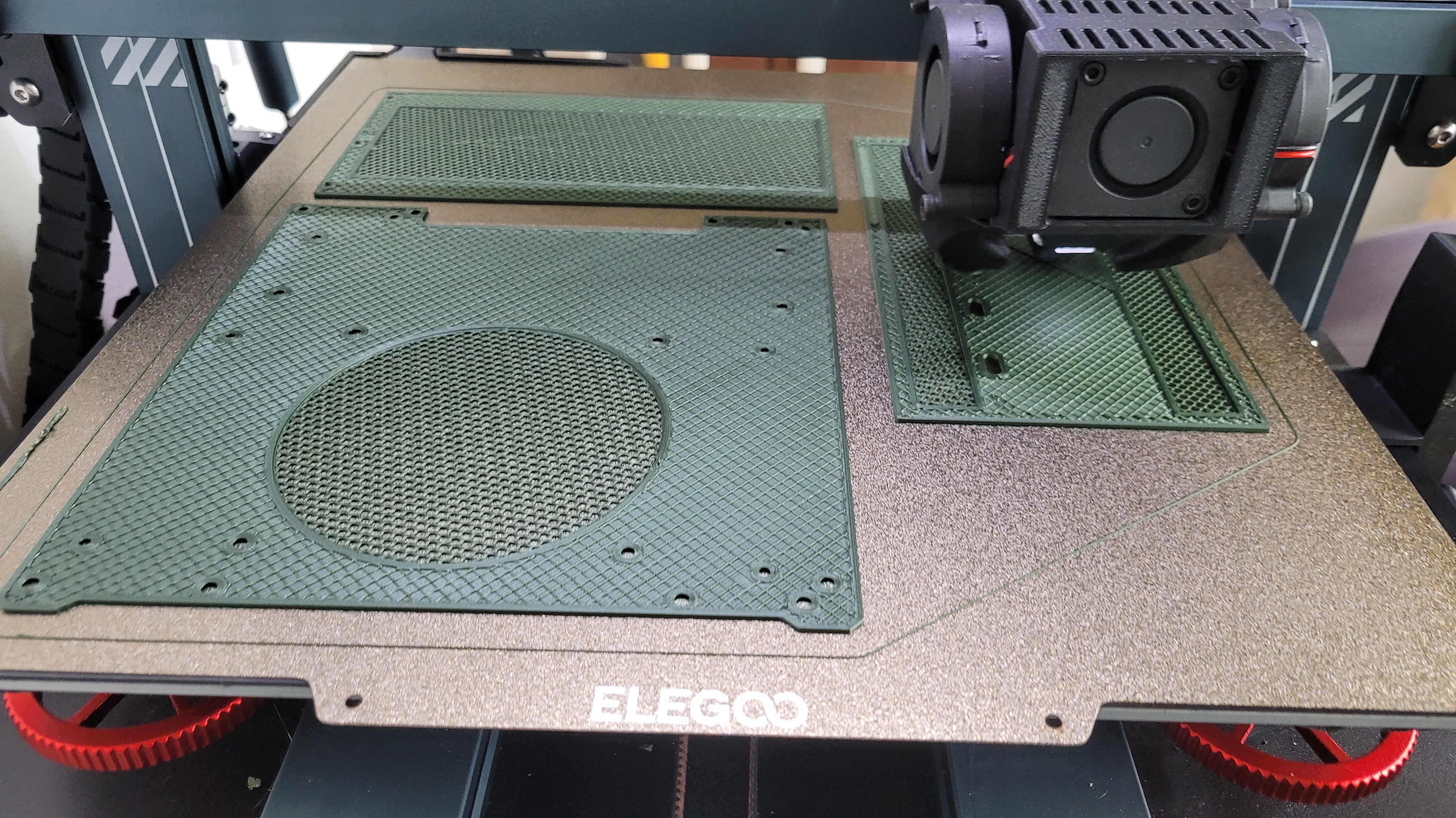
Vents
When did my first cad design I modeled the vents for the air flow. I learned however that I could utilize Prusa’s slicer’s own functionality to create much better designs quicker than directly modeling them. Instead I included a light outline of where I wanted to vents to be placed so that in the slicer I could align a modifier.
Hole positions
A big worry of mine was getting the hole pattern correct for all the various components. Fortunately for me mITX is a standard and finding a pdf diagram of the hole pattern was easy. The PSU also had detailed design drawings as well as an available cad model that I could import. Unfortunately the GPU was a different story as it clearly was never meant to be DIY for this purpose.
In order to replicate the hole pattern I utilized my calipers to measure the greatest and shortest distance path to the holes and taking the average position to get the hole to hole center distance. This was tricky for the longitudinal direction as the holes were at different levels.
In order to double check my work I printed the pattern out 1:1 to verify with my GPU before I went ahead and 3D printed the parts.
Build
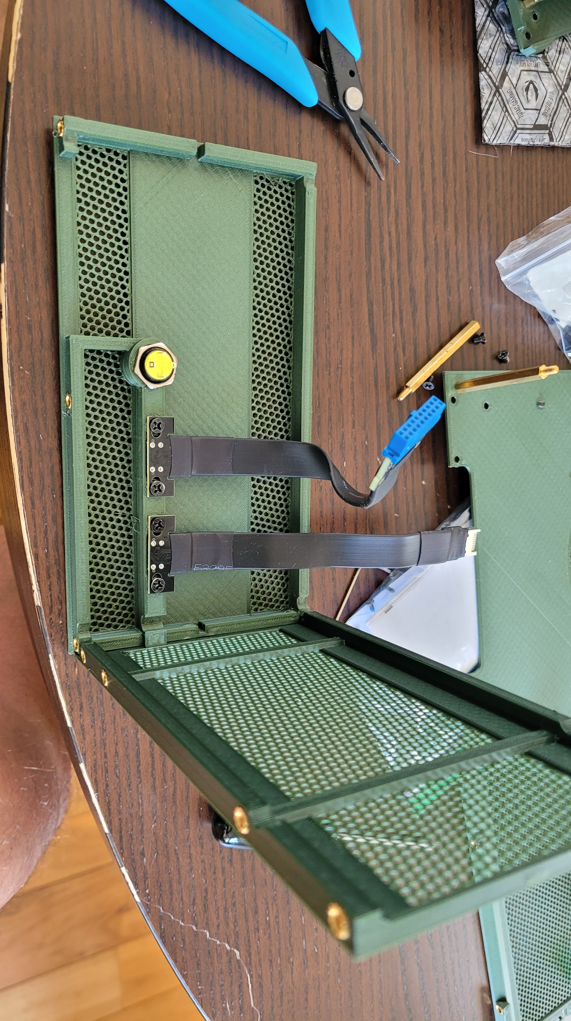
GPU Panel
After 3d building all the parts (and a few test iterations to get things right) I began to assemble the parts.
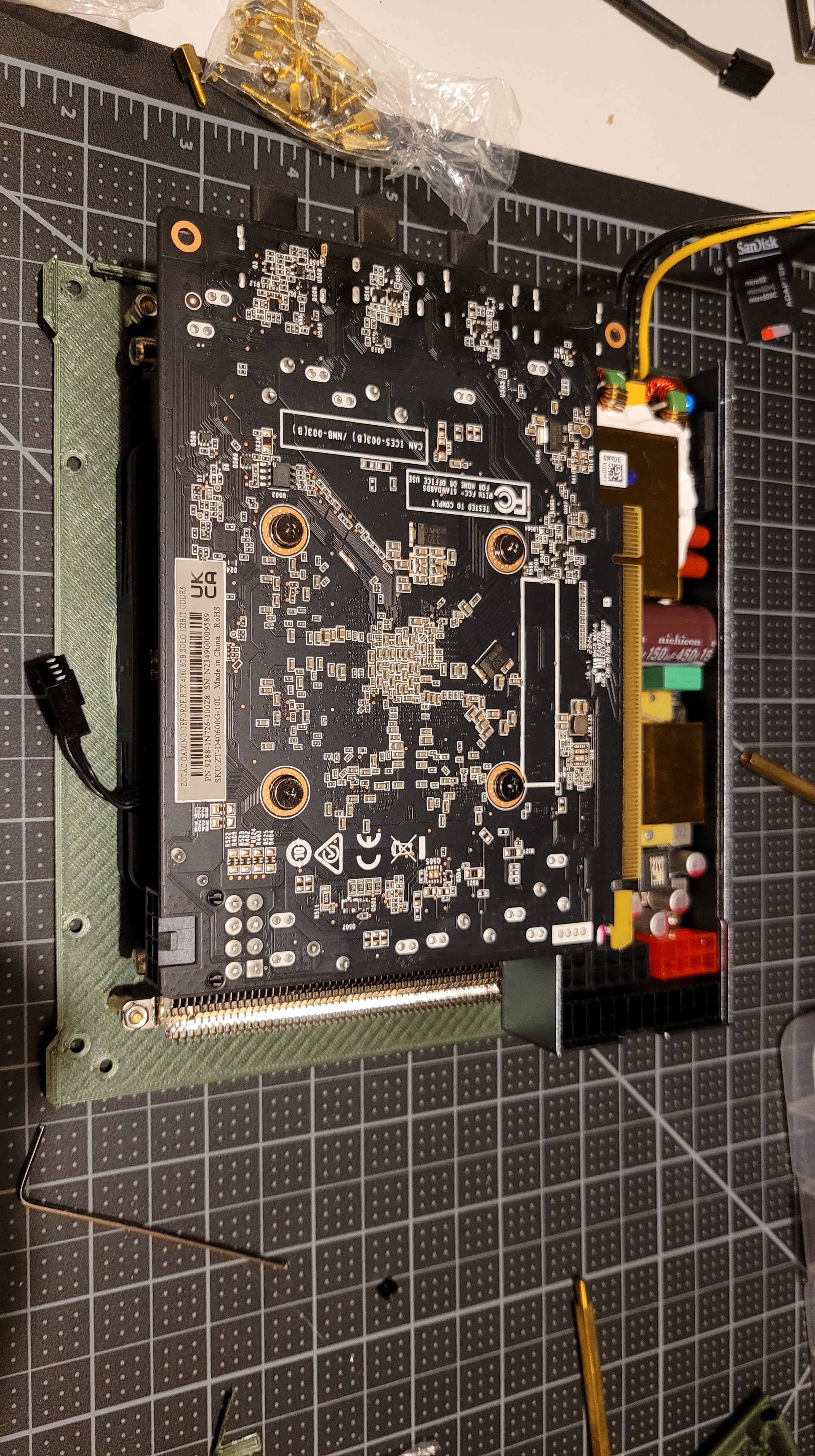
First up was the GPU panel which consisted of the PSU and the GPU. The GPU was integrated to the panel utilizing M2.5 standoffs and screws. To accommodate the heatsink height differential I found that adding a M2.5 nut was enough to space things appropriately.
Then the PSU was mounted utilizing M3 screws.


Front Panel and Motherboard
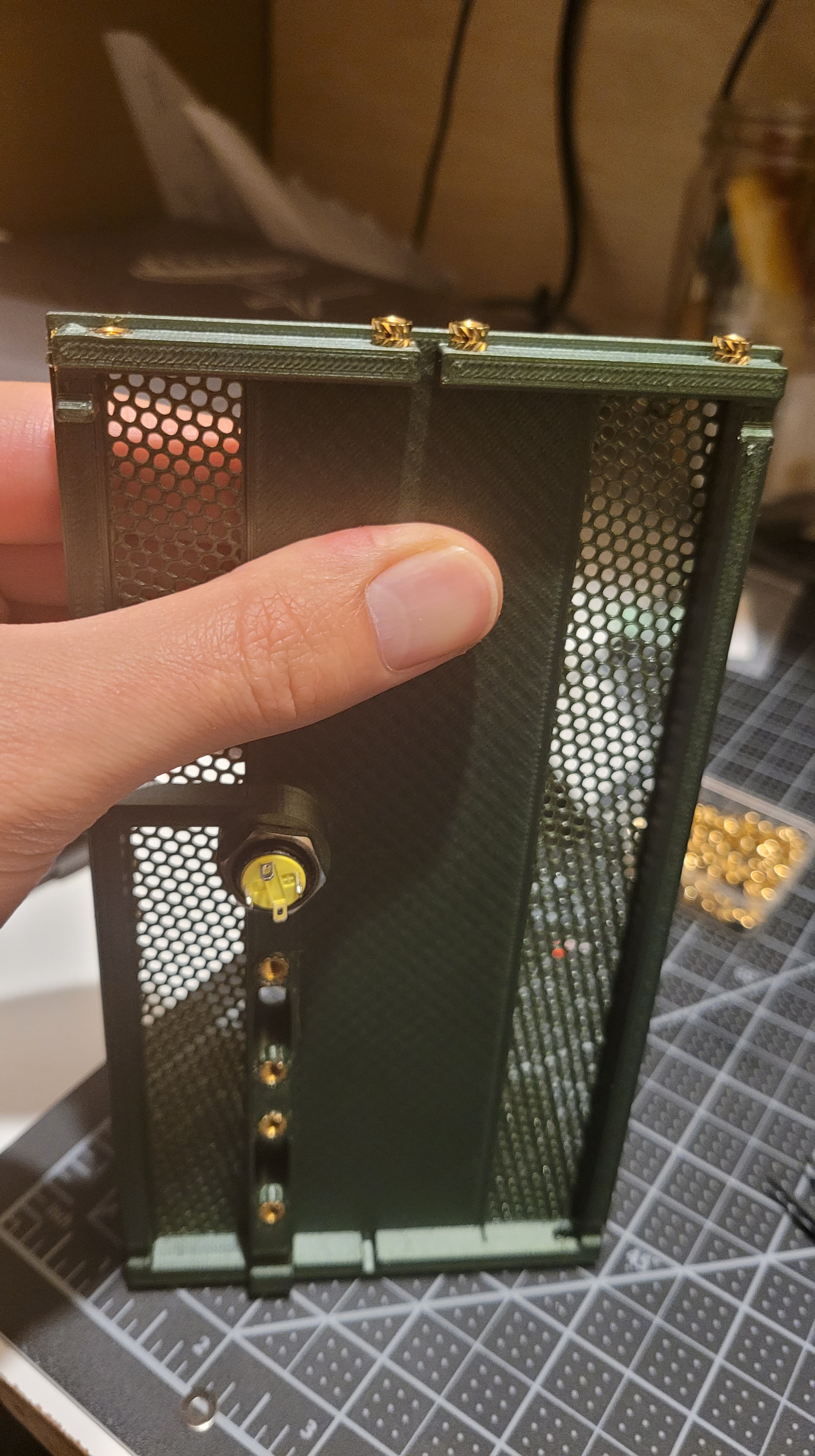
The front panel consists of 2 USB3.1 ports as well as the power button. In the design I lined the ports up to the motherboard’s interface which was relatively tricky as the cable bend radius for the USB ports were not very flexible. Fortunately I designed just enough cable clearance to be able to get things to slot appropriately.


Inserts
The interface between the plastic components utilize M3 threaded inserts. Super simple to create a hole within the design and to use a soldering iron to melt/embedd the inserts into the part. I designed it so that the GPU and CPU panels have the screw holes while the front, top, and bottom parts hold the threaded inserts.
Standoffs
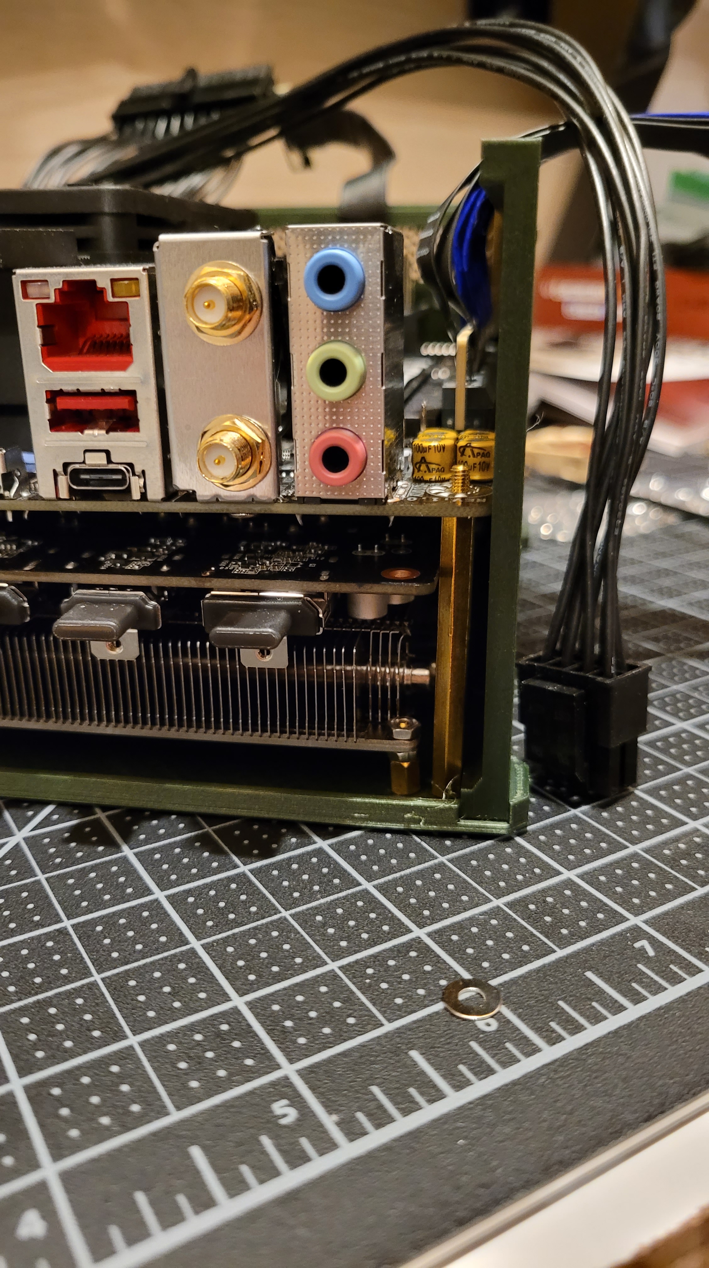
As mentioned in the design portion I’m utilizing the motherboard PCB as the backbone of the assembly. In order to transfer the loads from the side walls I’m utilizing 40 and 44mm brass standoffs. In order to help reduce any possible PCB crush I threw in a washer toward the PCB to help reduce the pressure caused by any tilt of the standoff when things are moving around.
Kapton Tape
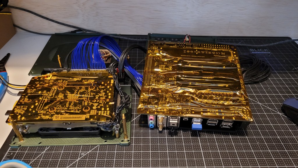
The clearance between the motherboard’s PCB and the GPU’s PCB is very tight. I measured on the order of 3mms. Plenty of room for the PCIE 4gen riser cable, but tight enough to make me nervous of any shorting risk. This is especially the case for the CPU and GPU back plates that get fairly close to each other. To help make me feel better I applied a layer of 2 inch wide kapton tape to the back to act as an insulator. Its high temperature adhesive properties helps alleviate concerns of the adhesive peeling due to high temperatures. Nothing should ever get hotter than 90deg C, but good to have some margin.
Harnessing
The harnessing of the PC was a somewhat interesting task to accomplish. As mentioned previously the USB front panel cables were tough because of the bend radius and clearance to both the GPU and motherboard.
The PSU to Motherboard cable was relatively straight forward. The PSU came with ~2inch long harness cable. I designed the parts so that the ports lined perfectly up with the each other in the sandwich configuration.
The CPU power cable was also relatively straight forward as the cable had plenty of clearance between the CPU panel and the CPU heatsink. The most difficult thing about the cable was that it was so long and I was reluctant to cut and modify it. Fortunately a few zip ties and a switchback solved the problem. Might go in and cut it shorter later to help with airflow, but it’ll be shaving mWs off so probably not.
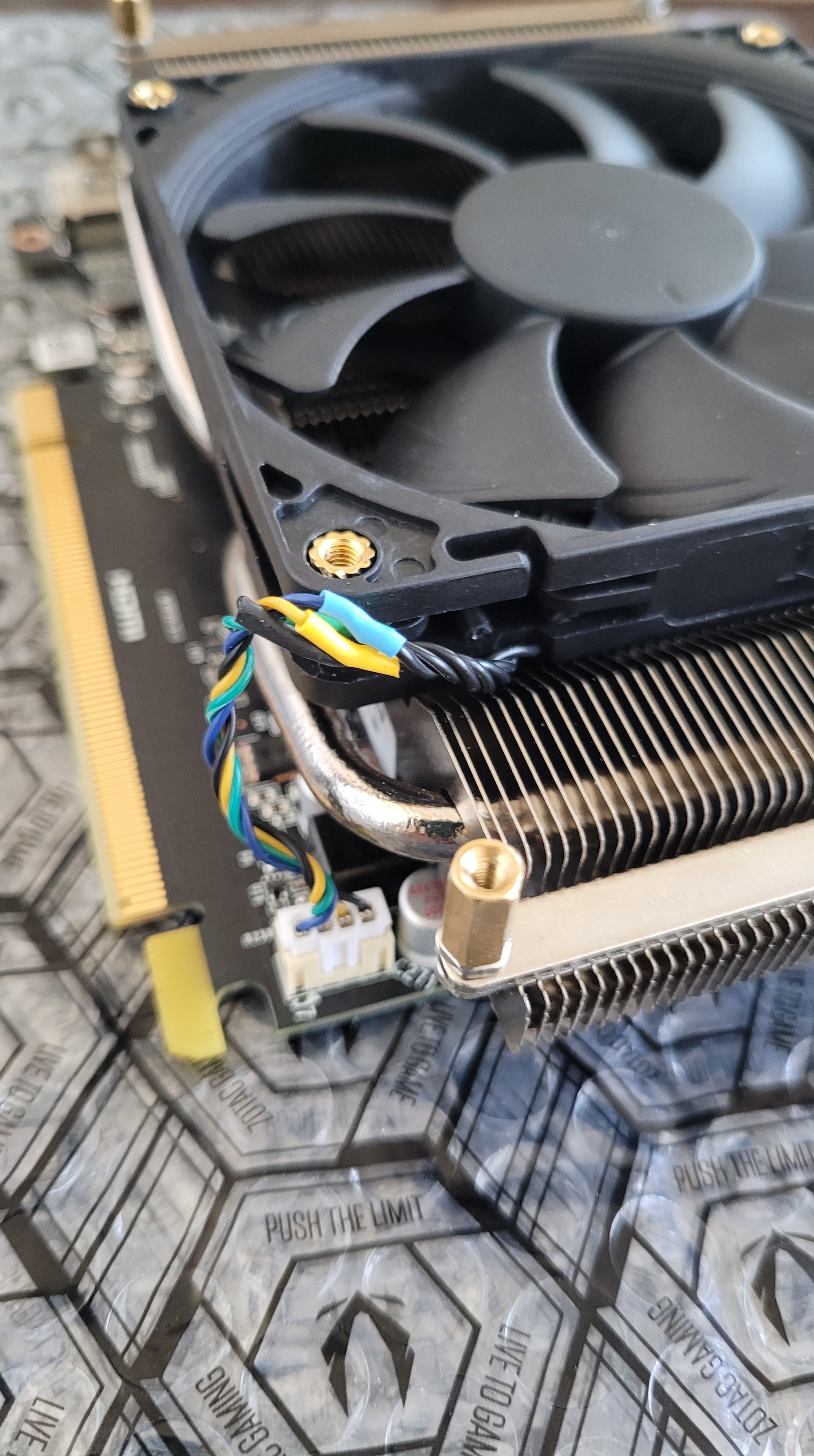
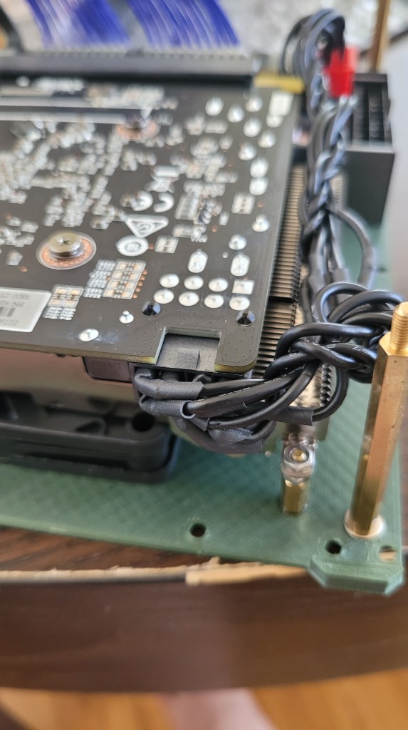
The GPU power cable was a real challenge. The problem is that the GPU port was never meant to be in this specific position. Traditionally the GPU would be pointed outward with plenty of case to GPU clearance for a cable to snake its way into it. However I had positioned it upside down into the ground so I had very little clearance. Even custom PC cables from modify shops were way to big.
The solution ended up being somewhat barbaric, but functional. Really the problem wasn’t that the connector was to big, it was the connector plastic housing that was too large. The pins were totally fine given that when inserted they were essentially interleaved on top of each other. Thus the solution to the problem was to extract the pins, individually heat shrink them, and then insert them into the connector. The resulting clearance needed was only the wire bend radius, which gave plenty of headroom.
What also gave me a headache was trying to find the correct pinout for the PCIE-8 power connector. In the end I utilized this website and close examination of the connector housing. Each pin actually has a different shape that helped serve as a reference when looking at the drawing. It was also important to keep in mind the perspective of the cable vs that of the connector least you accidentally mirror the pinout.

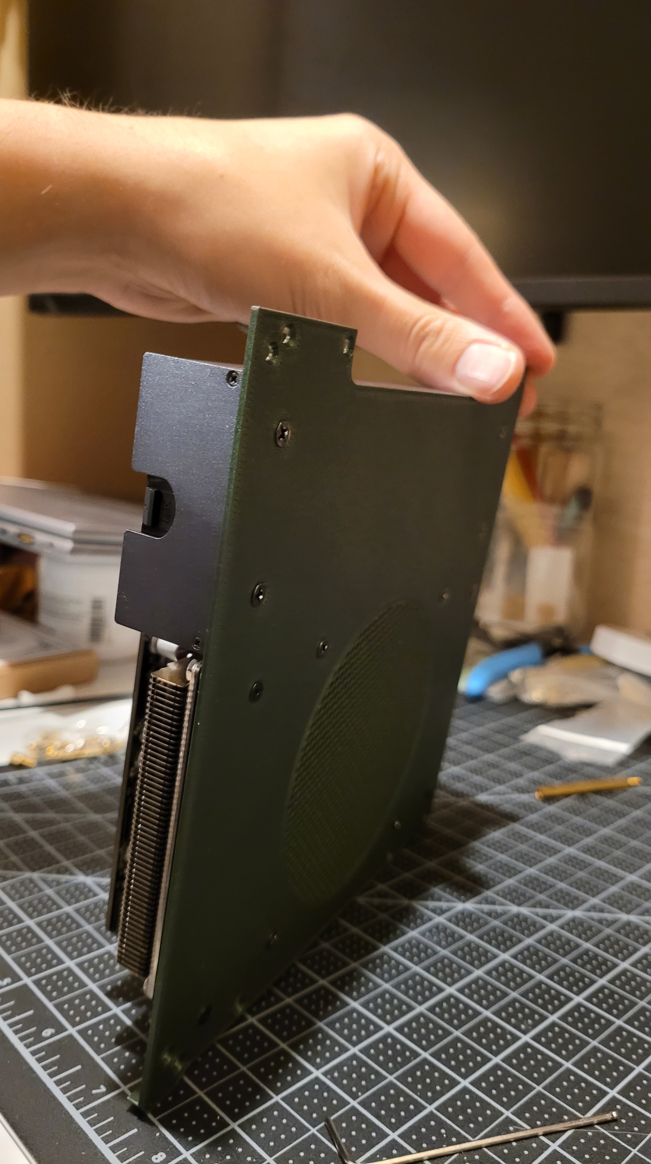
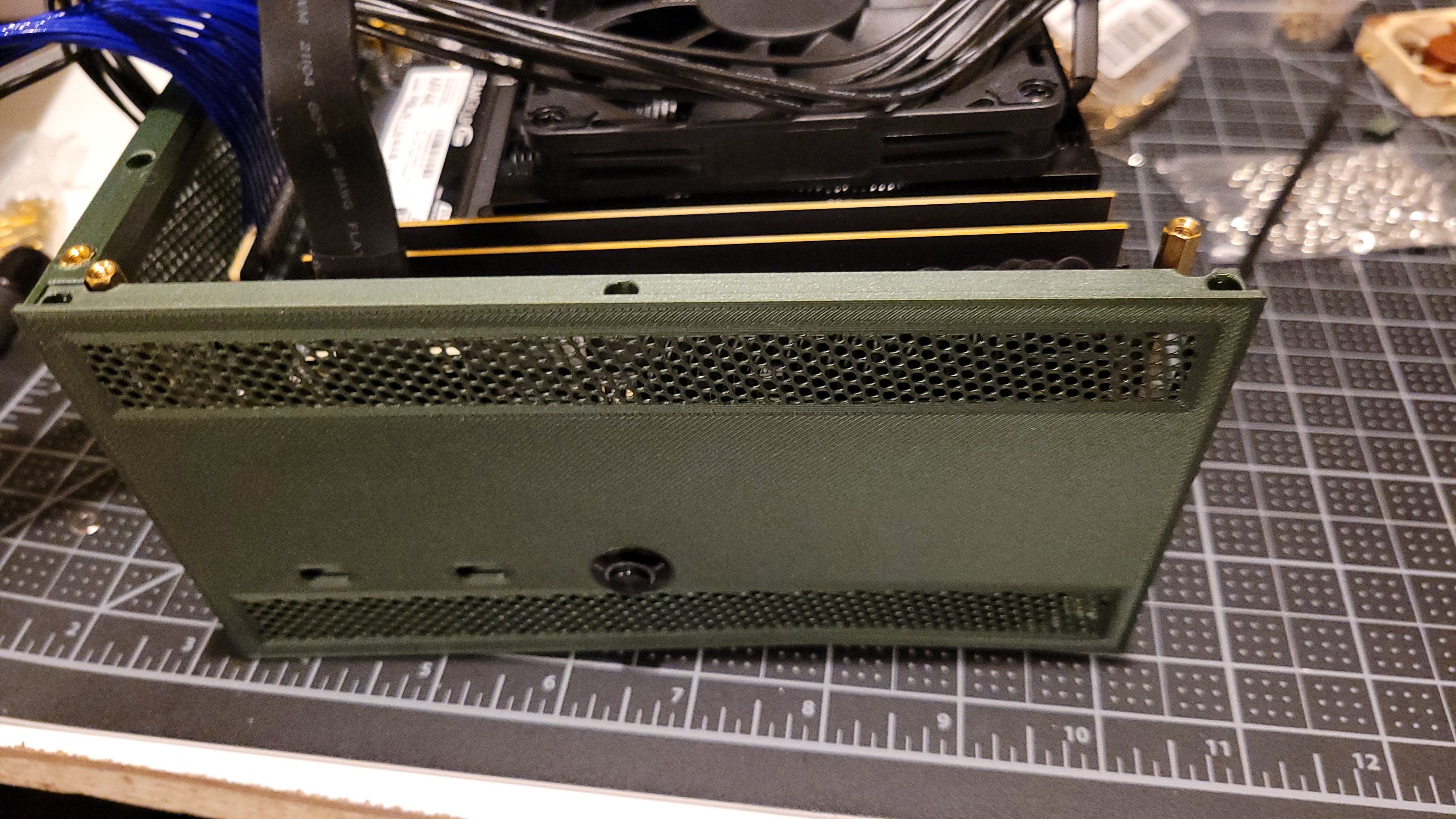
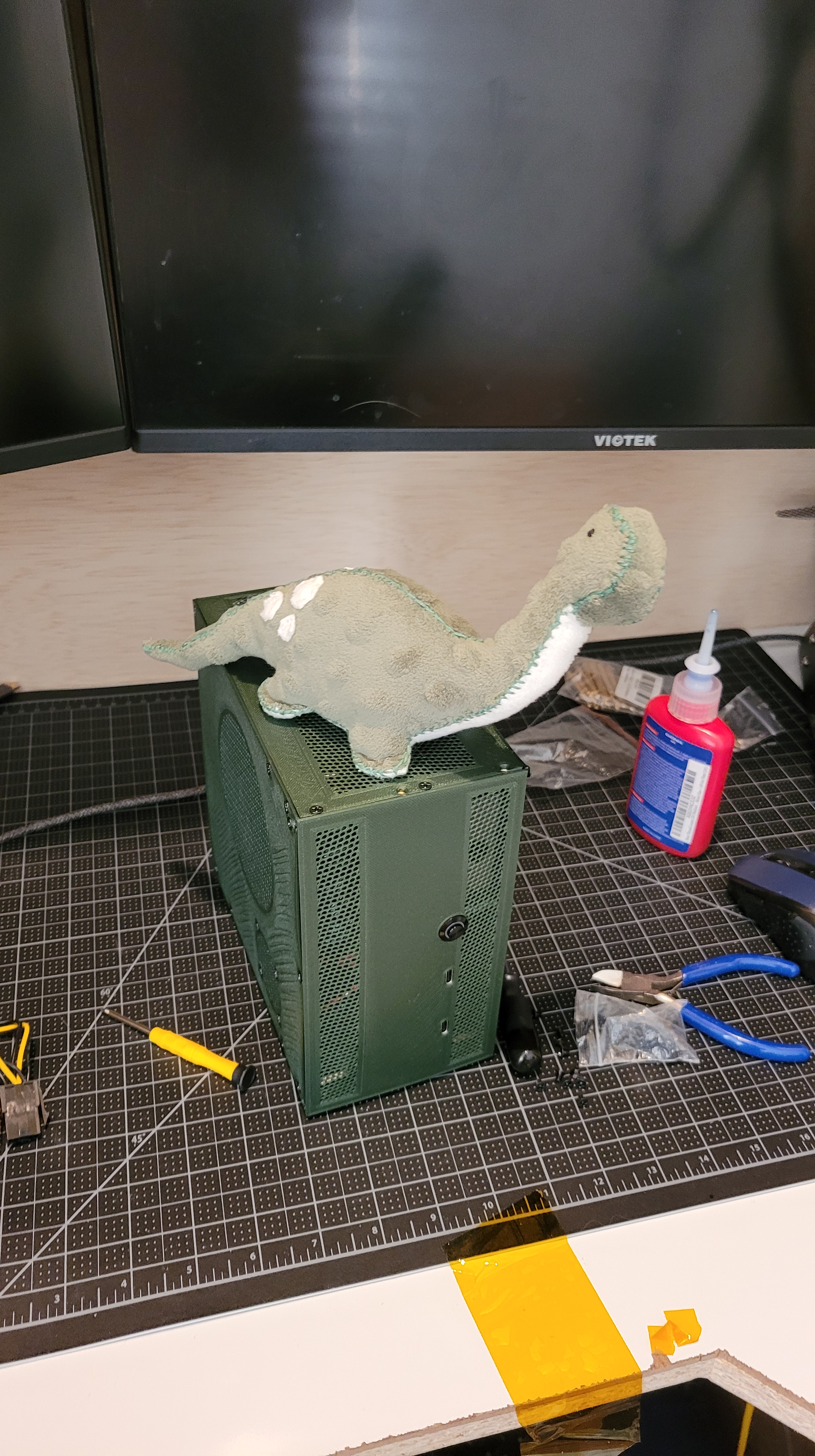
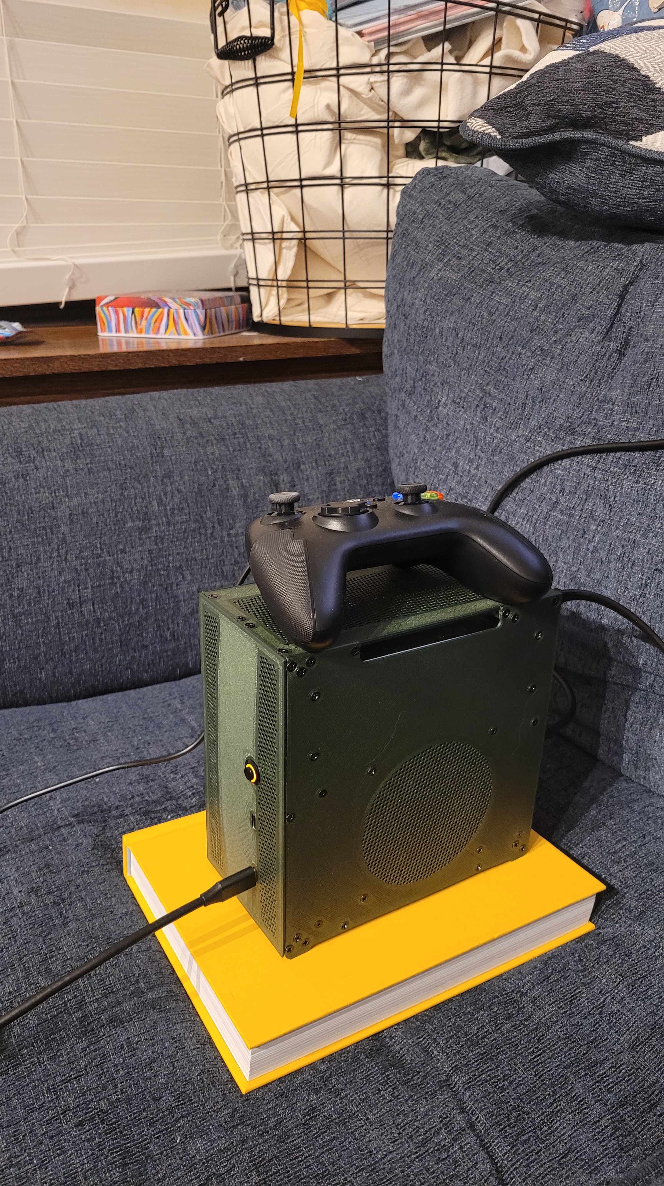
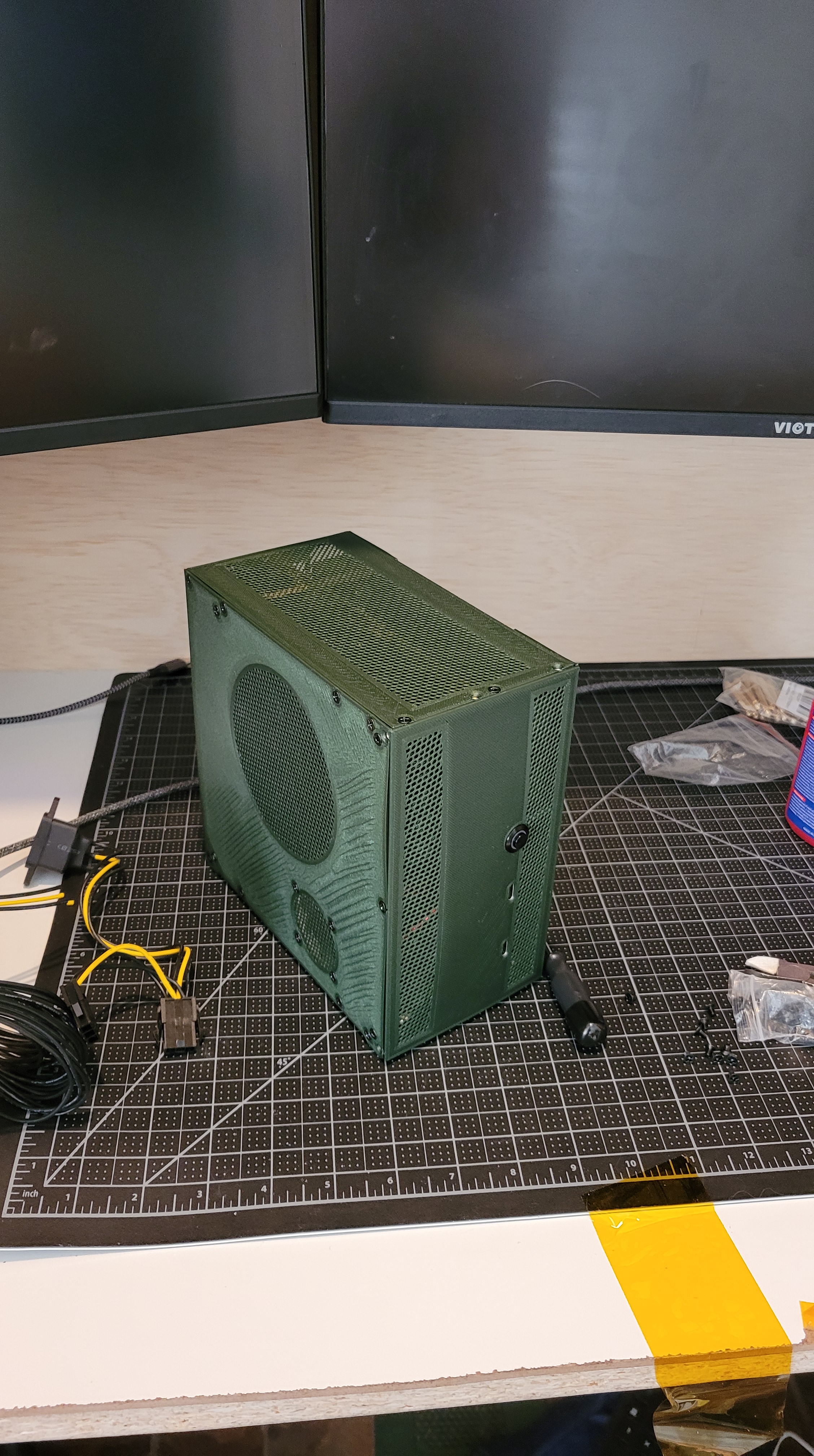
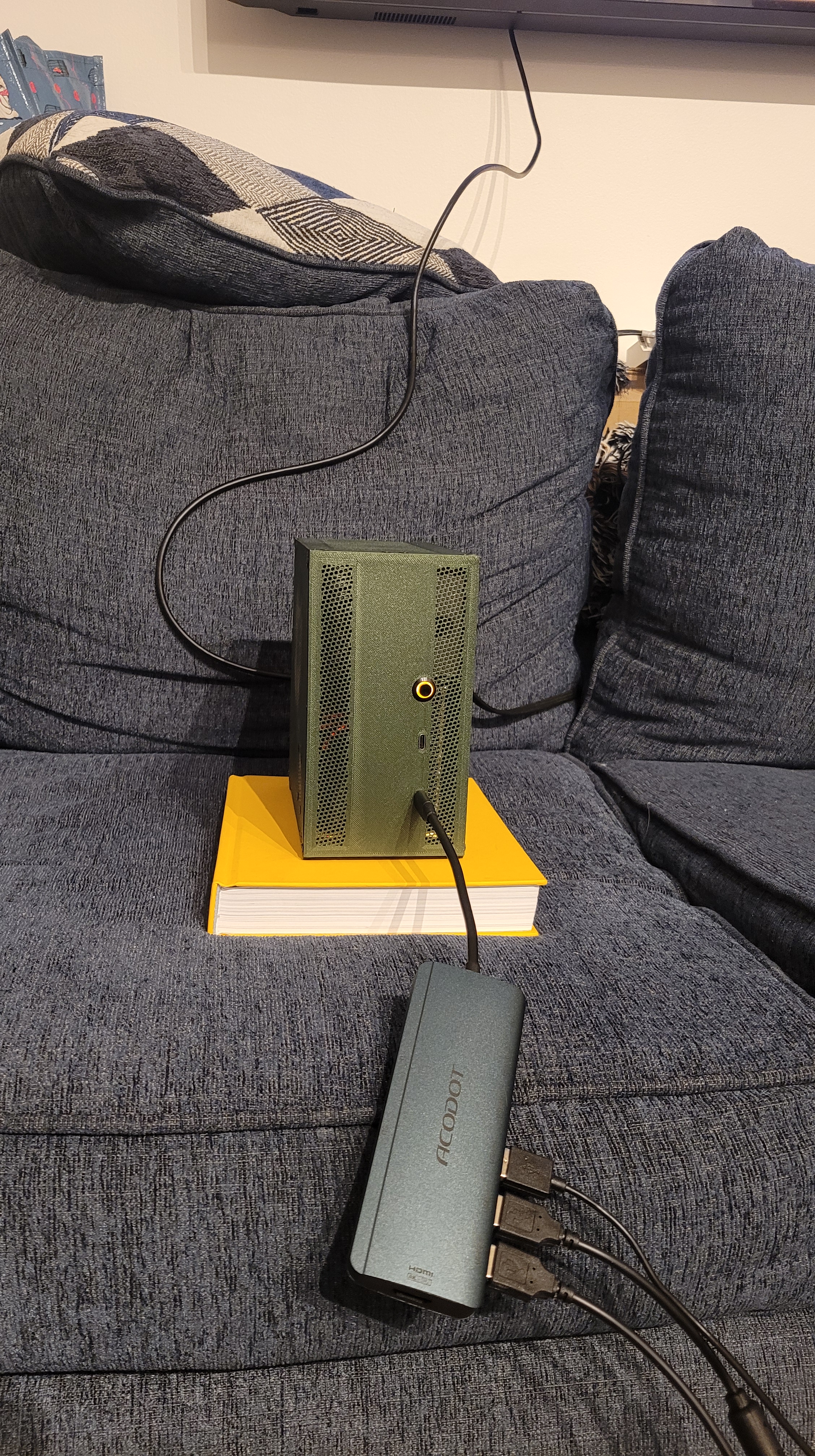
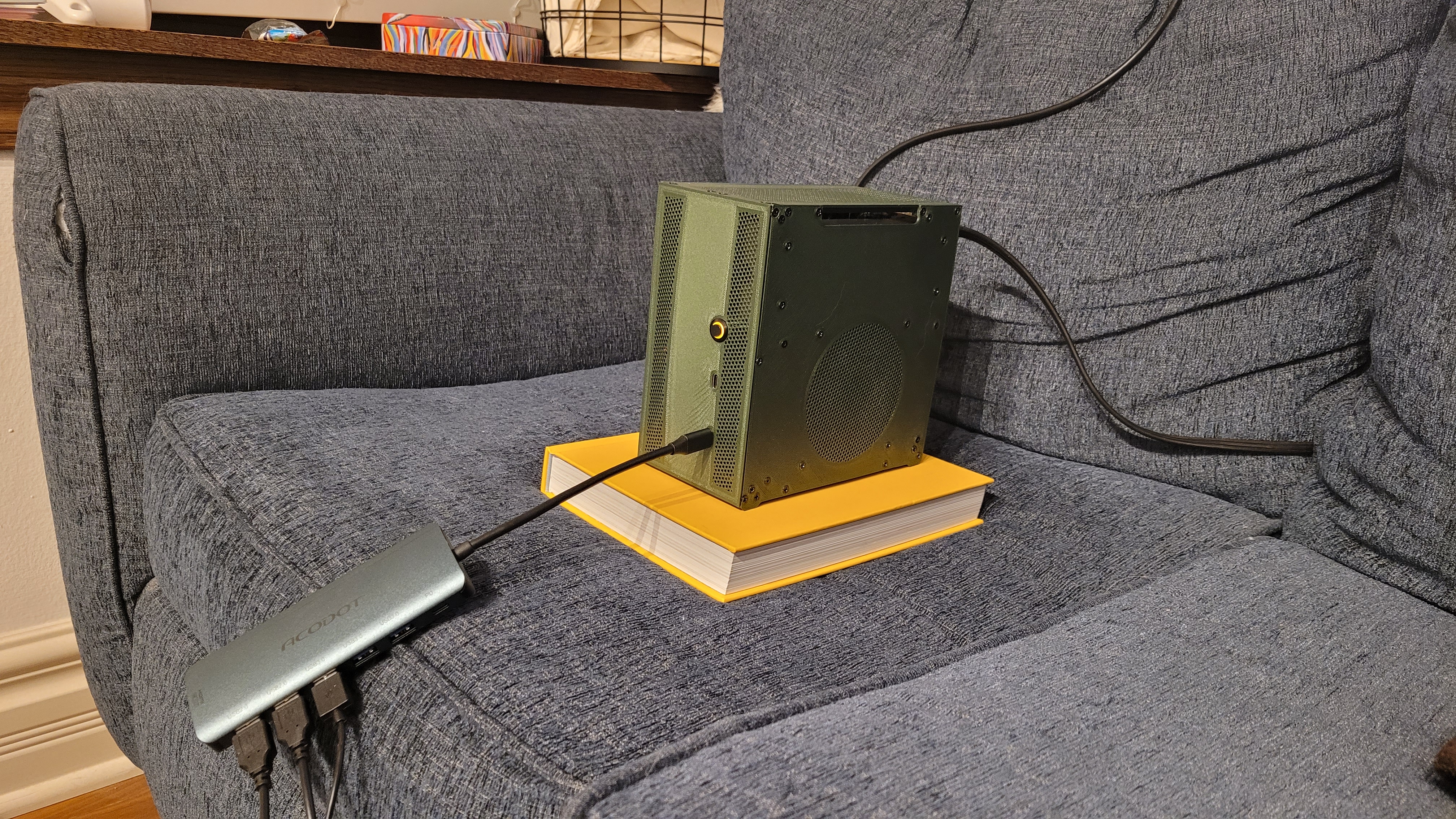
Results
Some pictures of the final thing! Very happy with how he turned out 🙂
Undervolting
GPU
When I was finished with the project I ran some stress tests and was actually very happy with the thermal performance. However I knew that there was some potential to undervolt the GPU while achieving the same performance.
Essentially the idea behind undervolting is that there exists a general operating profile that works for all RTX4060 video cards. However despite how precise silicon manufacturing is not all parts are created equally. What this means is that some chips could run at the same performance level while being set at a different voltage.
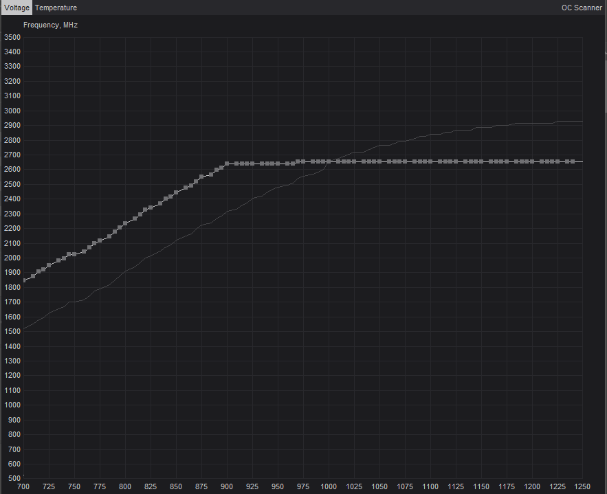
This profile is basically a voltage – frequency relationship. The chip understands when there are demands placed on it and thus increases its frequency in order to do more operations per second. At this specific frequency it sets the voltage that the core runs. Simply: More computation needed –> higher frequency –> higher voltage.
By restricting the voltage that it can set itself you can effectively reduce the total power consumption. The chip would still operate at the same frequency but at a lower voltage. In the end it becomes a game of finding the right balancing point. What is the maximum frequency and the lowest voltage that I can operate in a stable condition.
I utilized this website as a guide: https://sff.life/how-to-undervolt-gpu/
In the end I found a configuration where I could operate at 15% less power with only -1.9% impact to performance. This resulted in a 11.8% temperature reduction (71.8deg C vs 63.3deg C). For those specifically interested I utilized 900mV core at 2640MHz.
CPU
The same theory of undervolting GPUs is true for undervolting CPUs. In my opinion the CPU undervolting is more important than the GPU because the CPU is actually being thermally throttled. Essentially the Ryzen chipset configures its frequency/voltage relationship just like the GPU, however for the CPU it actually hits the thermal limit. This is one reason why the TDP is only 65W, because the device is physically forcing itself to not go beyond it.
The best answer to this problem is really to use better heatsinks/cooling strategy. However with my limited volume there’s only so much room to work with. I did my best to configure the vents so that we could maximize heat rejection, and I even fitted a secondary 25mm fan on the CPU side to help.
Another thing I realized only while I was attempting to configure the CPU undervolt was the A series motherboards like the one I had purchased actually doesn’t come with that option. This is because AMD doesn’t support/allow over-under volting control on first generation motherboards. Which is a big bummer but makes sense when you want your initial flagship product to ship without complications of people messing with things.
Fortunately for me I found that if I reverted to an older version of the BIOS the option did appear! Did it actually do anything? Hard to tell because of the general 65W TDP throttle, but I think it only helped marginally. Lesson learned for next time!
Lessons Learned
A few lessons that I learned
- M3 screws are overkill. Honestly could have gotten away with M2 with the added benefit that the insert diameters are smaller.
- Use more screws! I was being a little conservative on the screws/inserts on the front panel. The result is that there’s a slight bowing affect caused by the cabling because the plastic stiffness in the thin direction is verrry low. Adding some more screws would have eliminated this problem by reducing the span.
- I designed a handle into the gpu panel, but my fingers are too thick. Just needed to space the PSU down by 2-3 mms and that would have solved my problem.
- PSU cloverleaf power input is floppy. The lever arm on the power plug results in a bendy plug. I could stiffen this up much more if I added more material behind the PSU. Wouldn’t have made any volume changes but made the connection more rigid.
- Use B+ series motherboards. This goes to the undervolting of the CPU, need a higher generation motherboard to get this to work properly.
- Larger CPU cooler. Honestly I was a bit disappointed with the Noctua low profile cooler for a few reasons. because of the orientation of the fins the air gets blown straight across the VRAM sinks (Good), but also directly into the DDR stick (not good). It would be great if there were a fin orientation that allowed 90degree exit out the the back (vram) and top (nothing). Additionally there’s a lot of dead space within the case over the SSD drive. This space could easily accommodate a 120mm fan which because the area increases by the square of the radius would have resulted in much more air flow (m3/hr). Maybe a future project would be to modify a heatsink to fit this space and or design my own.
