This project was undertaken because I had a self-wound inductor for my EFNMR project. Initially I was manually adjusting my function generator and recording data with my oscilloscope, but for many frequency points this becomes an arduous exercise. Fortunately I learned that Siglent products have network capability and can utilize the VISA protocol that NI developed.
Network Setup
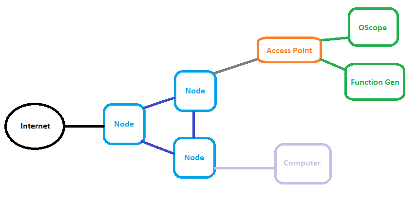
The oscilloscope that I have is a SDS11D4X-E and the function generator is a SDG1032X, both of which are entry level instruments manufactured by Siglent. Each machine has an ethernet port which I wired into a netgear router configured as an access point. This access point is wired into one the nodes of my wireless mesh for which I configured static IPs for both machines. The overall physical network can be seen below.

Environment Setup
As a python enthusiast I was happy to find a module made to interface with VISA. The overall setup installing NI VISA and drivers was very simple. The docs can be found here: https://pyvisa.readthedocs.io/en/latest/ .

Script Setup
The script I wrote for this project can be found here: https://github.com/ovdessel/PyVISA_Instrumentation .
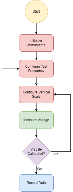
Essentially what happens follows the flow diagram outlined to the right. After the initial configuration the script iterates through a series of frequencies. At each frequency point it configures the oscilloscope’s vertical scale so that the maximum of the waveform appears near the top of the scale. In doing so we can utilize the full-scale accuracy of the 8 bit converter. After the scale is calibrated we record the data multiple times. We do this by ingesting the waveform and perform a FFT to determine the magnitude and phase of the collected data for that frequency point.
This website was a great reference point and a refresher on phasors: https://meettechniek.info/passive/parasitic.html
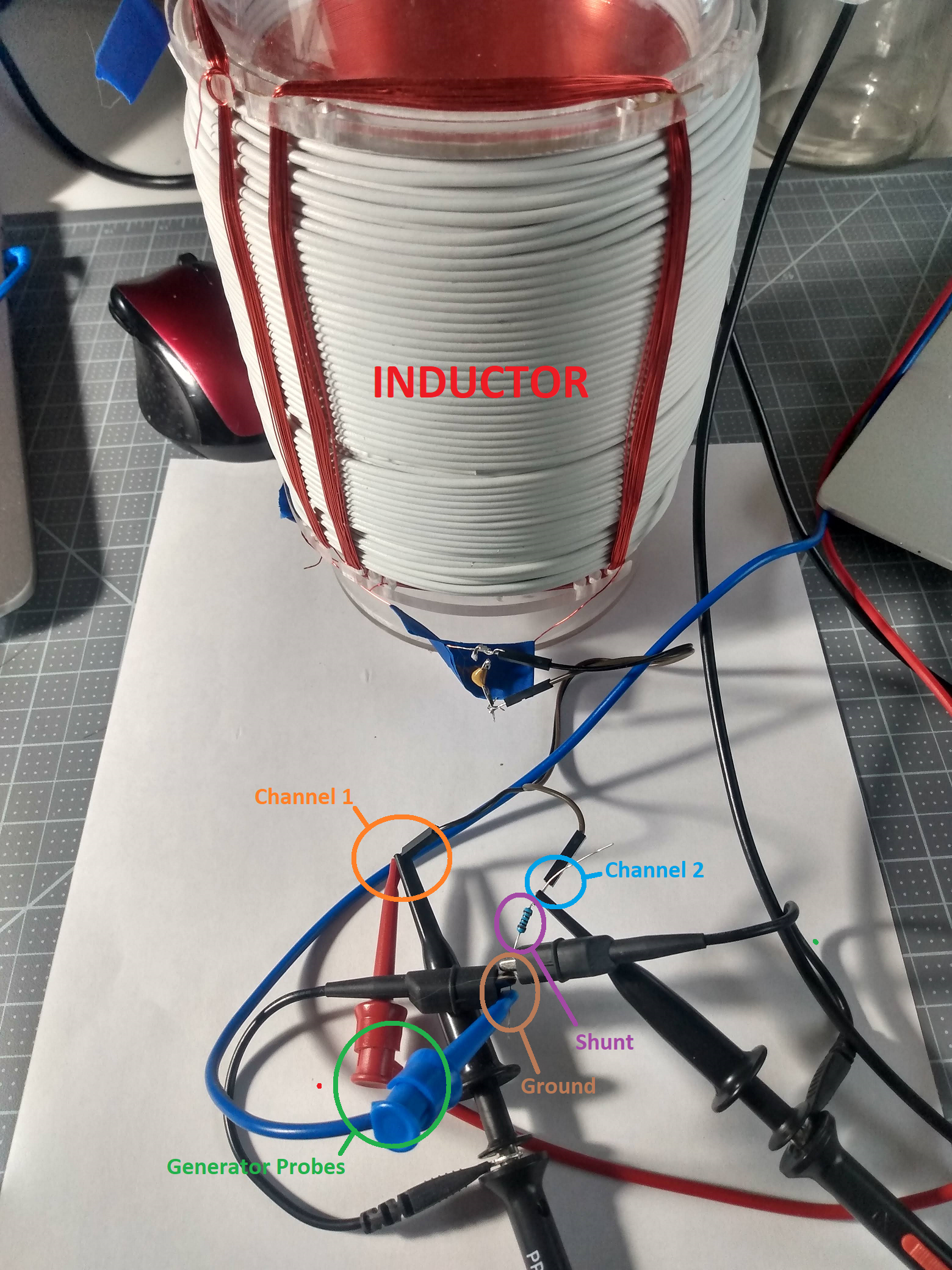
Measurement Setup
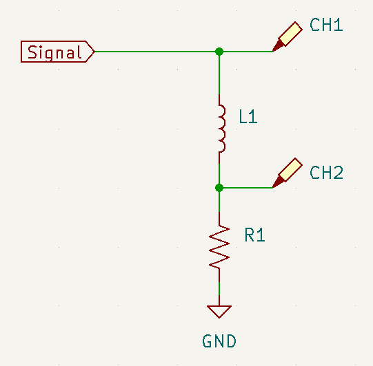
Unlike the reference website from meettechniek I did not have a current probe. However, I do wish I did have a current probe, but unfortunately they’re expensive so in the meantime I utilized a shunt resistor. Unfortunately this meant a couple of things:
- The resistor has non-negligible inductance and capacitance.
- The smaller the resistor the better the parasitics, but the worse the current reading as the voltage drop is lower.
I tried a variety of resistors from 2-2k ohms with mixed results given known inductor values.

Data Collection
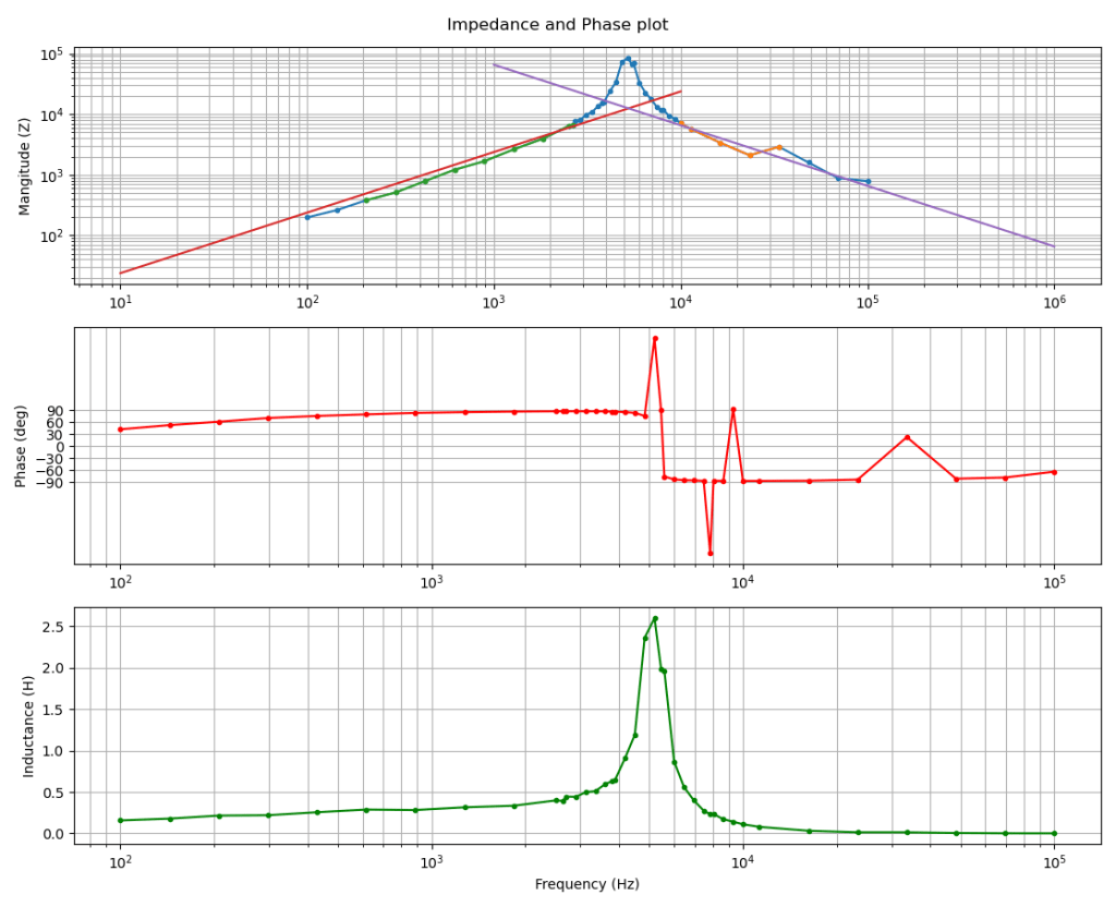
After collecting the data the script automatically reports the impedance phase plots and attempts to analyze the inductance and parasitic capacitance given the slope of the log-log chart.