I got myself 4 old server rack power supplies and I’m working on a project to utilize them for a high voltage source. These pieces of hardware are amazingly cheap off ebay which makes sense given the number of servers around the world.
Each DSP-600pb is rated at ~12V and ~47A meaning a total of 575W of power. The goal is to utilize 4 of these within an adjustable configuration to provide power for any project that I can come up with. Hopefully 2.3kW is enough power!
An interesting feature of these power supplies is that the output voltage can be regulated. This post https://endless-sphere.com/forums/viewtopic.php?t=47415 shares an amazing project put together for high current charging of lipo batteries.
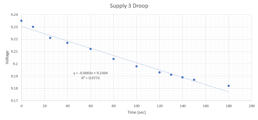
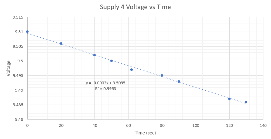
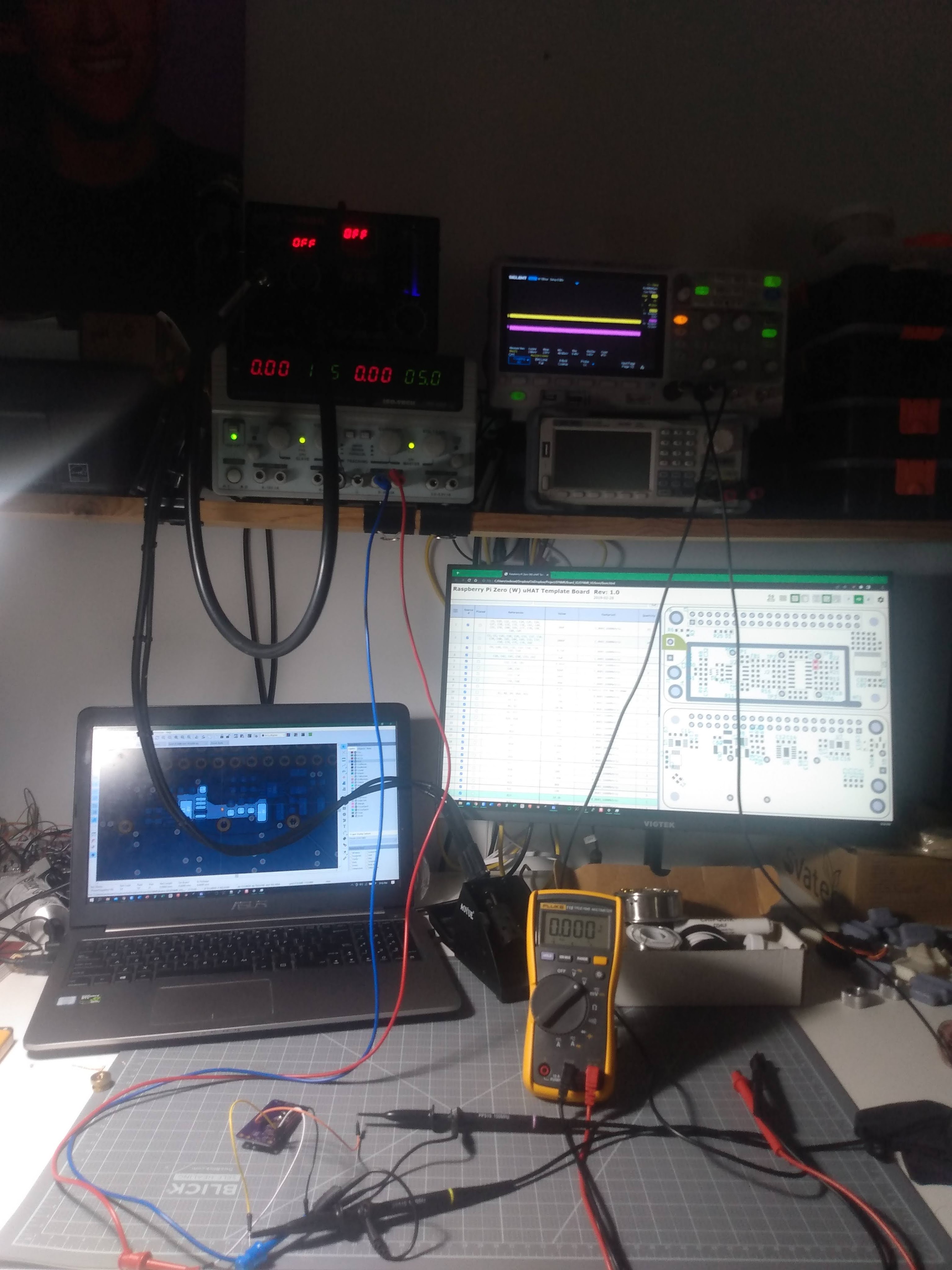
I undertook my own experiments to determine when the power supply becomes unstable and looses regulation or triggers the protection circuit. I utilized an electronic load and a 100k pot that I slowly adjusted.
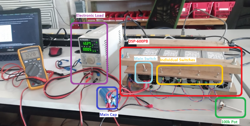

The results of this test can be seen in the charts below. I was in a time crunch so I tested only 2 out of the 4 supplies which should give me enough data to get a general sense of the output adjust range. Overall these power supplies have a rather limited adjustment range.
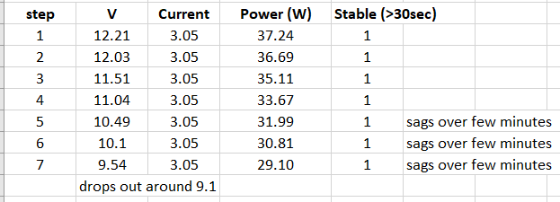

The one thing I did notice that although these supplies can be stable over 30 seconds, they tend to droop over time. And when they hit the threshold voltage they will automatically shutoff. From these tests its evident that the useable adjustment range is only around 10.5 – 13.5V. Note that I didn’t try going above 12V, but from my research raising the voltage seems to be easier.