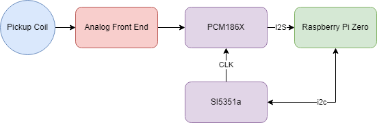
With the board assembled and the filter issues figured out the next step is to figure out the digitization process. For this we’re using a PCM186X family of audio analog converters which relies on utilizing the I2S protocol. In addition to the PCM186X device I’ve also got a SI5351a frequency generator in order to have fine control of our sampling rate. Overall the connectivity is shown below.
One important thing to note is that we are utilizing the PCM186X in master mode whereas the Raspberry Pi Zero I2S is in slave mode. This allows us to use a more accurate clock source than what is available on the pi.
Setup
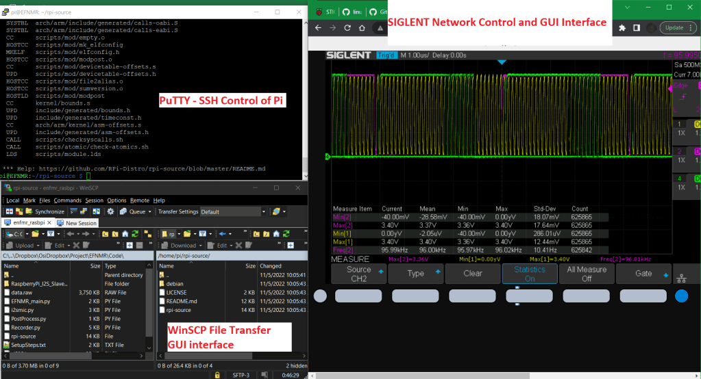
I used to be more of a bare-metal microcontroller guy, but I’m starting to really enjoy the flexibility of utilizing a single board computer running linux. The greatest thing about it is that remotely managing my devices is verrrrry easy! I can sit on my couch while my pi and scope sit on the bench in the other room. Some of the tools that I employ include PuTTY, WinSCP, and my scopes over-the-network control functionality.
SI5351a
The SI535a is a very easy to use frequency generator and is basically a 25 or 27 MHz crystal with a PLL and fractional divider. I started with using the adafruit si5351a library however modified it so that I could specify a 27MHz crystal rather than the 25MHz crystal.
Using my scope I could verify the frame frequency which is equivalent to the sample rate.
I2S
Initially I was hoping to utilize the basic configuration for i2s sound input but I’ve run into a few snags that I’m still trying to troubleshoot. It seems like the default method to record is to configure the I2S port on the Pi as master mode, which conflicts with the PCM1861 trying to drive the signals. In the end I get very odd waveforms which manifests itself as a low voltage threshold of 2V. Troubleshooting is ongoing.
